Design of circuit schematic diagram of single-chip microcomputer system
Develop the minimum system of single-chip microcomputer, and learn the crystal oscillator circuit, as well as the working principle and use method of the reset circuit in the development and utilization, learn some principles and applications of the minimum system of single-chip microcomputer, and then learn the functions and uses of the four interfaces of the 89s52 single-chip microcomputer, and use them. The smallest system of single-chip microcomputer is used to control the led lights and realize the pattern change we want. Learn how to use the electric soldering iron during the board making, and realize the combination of knowledge and practice, so that the components can be evenly distributed on the circuit board, making the product both beautiful and practical. Secondly, we must learn to use software to load the written program into the 89s52 single-chip microcomputer, and to realize the operation of the program through debugging. According to the connection diagram of the minimum system of the single-chip microcomputer, the welding and debugging of the minimum system of the single-chip microcomputer are completed. Master the use of keil microcontroller related software. Understand the working principle of the small system and master the practical application of the single-chip small system.
1...Main circuit:
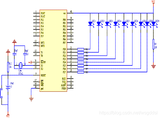
8 The first LEDl light adopts the common anode connection method, and its positive pole is connected to the +5v voltage vcc. There is an LED light led9 as the indicator light of the power circuit, and the LED9 light indicates that the power circuit is working normally and outputs +5v If the voltage is off, it means that the power supply circuit is not working properly. LED9 is also connected with a common anode. The anode is connected to +5v voltage, and the cathode is connected to ground through a load resistor R9.
The power supply circuit adopts a bridge full-wave rectifier circuit, which is rectified, filtered and stabilized to output +5v DC voltage. The output +5v voltage is connected to the anodes of 9 LEDs, and is also connected to the vcc40 pin of the 80C52 and the access program storage control pin 31.
The P2 port of 80C52 has two purposes: general-purpose I/O interface or high-order 8-bit address bus. The selection of the working state of the P2 port is controlled by the internal analog switch signal.
In the address bus state (A8-A15), when the instruction is fetched or the external memory is accessed, the analog switch is turned to the left, so that the output driver is connected to the Q end of the latch. The original data will be restored on the pin. This circuit diagram is the general I/O dual input and output function using the P2 port. When the P2 port is used as a quasi-bidirectional channel I/O interface, there are equivalent pull-up resistors (about 20-40KΩ) inside the interface output. The load should be connected to a 220Ω-1kΩ resistor to +5v as a pull-up resistor. When the output is low, the P2 port can accept a sink current of 50A. The anode of LED1 is connected to +5v voltage, the cathode is connected to the current load R1, and the P2.0 pin is connected in parallel, the anode of LED2 is connected to +5v voltage, the cathode is connected to the current load R2, and the P2.1 pin is connected in parallel, LED3, LED4, LED5, The connection method of LED6, LED7 and LED8 is the same as P2.0.
2. Crystal oscillator circuit and \ reset circuit: The
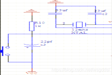
reset circuit consists of two parts: button reset and power-on reset. AT89 series microcontrollers are reset at high level. Usually, a capacitor is connected to VCC on the reset pin RST, and then a resistor is connected to GND, thereby forming an RC charging and discharging circuit to ensure that the RST pin has enough time for the microcontroller when it is powered on. Reset at high level, and then return to low level to enter the normal working state.
Button reset is to connect a switch in parallel with the reset capacitor. When the switch is pressed, the capacitor is discharged and RST is also pulled to high level. When charging, it will maintain a high level for a period of time to reset the microcontroller. MCS52 uses a 12MHz crystal oscillator as the oscillation source, because the microcontroller has an oscillation circuit inside.
AT89s52 uses a 12MHz crystal oscillator as the oscillation source, because the microcontroller has an internal oscillation circuit, so only one crystal oscillator and two capacitors are connected externally. , the capacitor of the reset circuit is a 33pf capacitor, the two capacitors are connected in parallel with the 12mhz, and then connected to the clock oscillation circuit of the circuit on pins 18 and 19. The oscillation pulse generated by the clock circuit is divided by two after the trigger.
3. Power circuit :
The single-chip microcomputer must have a good running state, and the power supply must be stable. If you don't have one, make one yourself.
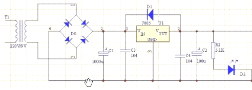
Component list: one transformer, two non-polar capacitors, two polar capacitors, one 7805, four 4007.
Connect the circuit to the circuit board according to the circuit diagram, and test the output voltage after completion. If the value is between 4.95 and 5.05, it is fine. If the output is not correct, check the output voltage on both sides of the 7805. Make sure that the output voltage is greater than 9v.
Transformer output, Change the high voltage into a low voltage, and the output voltage value is a sinusoidal pattern. The voltage after the rectifier bridge is rectified is a wave-like graph, that is, the negative half cycle of the sine is turned to the positive half cycle, and c1 rectifies and outputs an attenuated wave graph, because c1 is fully charged, 7805 is a voltage regulator module, and outputs a constant The 5v voltage, c3 and c2 filter out stray waves without common frequency, the output end of 7805 cannot be higher than its input end, so add a diode for protection.
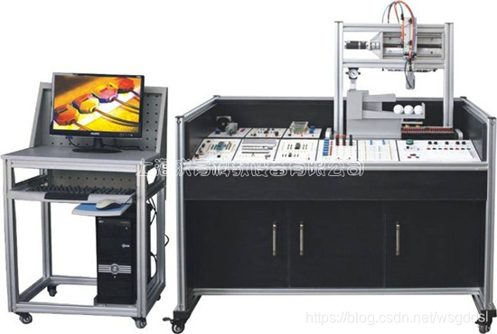
The QY-DPJ12 innovative single-chip integrated development training device adopts a module flat structure, and the single-chip microcomputer adopts Atmel's AT89S52. The microcontroller has 256Byte of RAM and 8KByte of FLASH, three 16-bit timers, two data pointers, and a watchdog circuit. 64KRAM expansion space, 64KROM expansion space; 32 IO ports, 6 vector interrupt sources; 0.33MHz operating frequency, three-level program encryption function; operating voltage 4.0V 5.5V. The use of DIP40 package is convenient for chip replacement and simulation. And it is designed with an in-system download design interface, which can be easily programmed through a USB downloader without removing the single-chip microcomputer from the circuit.
There is also a serial communication interface on the module, which has been added with a boost circuit, which can directly communicate with the computer. Philips MCU and Hongjing MCU can also download programs through this port. A manual reset button is added to the reset circuit, which can be directly reset. There is also an active buzzer drive circuit on the module, which can make a sound directly to a fixed level.
