Fire temperature-smoke alarm system design of MQ-2 and DS18B20, 51 single chip microcomputer, with simulation, C code, schematic diagram and PCB, etc.
Design requirements
- Master the software and hardware principles and general applications of 51 single-chip microcomputer;
- Master the working principle, production and control method of MQ-2 smoke alarm;
- Master the working principle, production and control method of DS18B20 temperature sensor;
- Master the working principle and usage of ADC0832 analog-to-digital conversion chip;
- Design a smoke alarm system based on single chip microcomputer, and measure, analyze and summarize its various functions and indicators.
System overview
In this design, MQ-2 smoke sensor, DS18B20 temperature sensor and AT89C51 single-chip microcomputer are selected as the core devices and combined with other electronic technologies. The AT89C51 single-chip microcomputer controls the sensor to detect the smoke and temperature of the detection site in real time, and the detection results are recorded as data. Information processing can realize the functions of sound and photoelectric integrated alarm, concentration display, temperature display and so on.
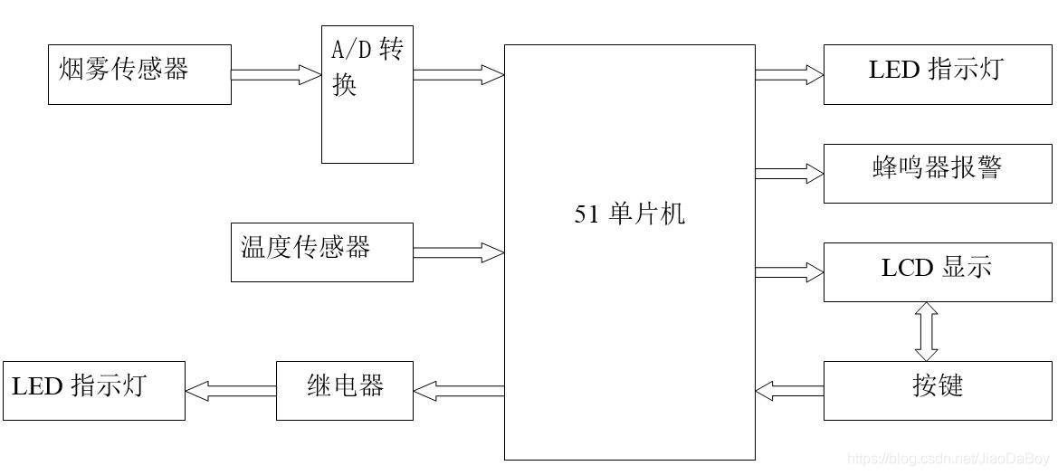
The components of the smoke-temperature alarm system are: MQ-2 smoke signal acquisition circuit, ADC0832 analog-to-digital conversion circuit, DS18B20 temperature signal acquisition circuit, single-chip control circuit, LCD display circuit, button circuit, relay circuit (in practical applications, the relay Circuits can be used to control electrical switches, sprinkler facilities and fire-fighting facilities, etc.) and sound and light alarm circuits. The system framework is shown below.
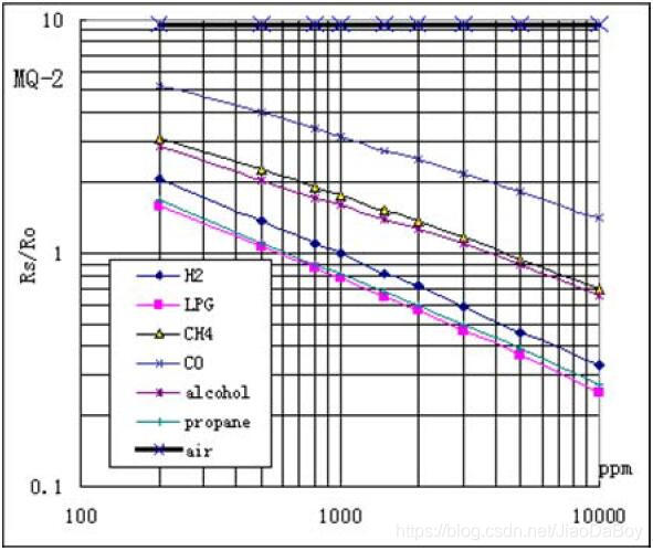
MQ-2 Sensitivity Characteristics
When the smoke sensor is exposed to the same type of smoke under the best working conditions, the characteristic that its resistance value RS changes with the gas concentration is called the sensitivity characteristic, which is represented by K.
K=RS/RO
In the formula, RS is the resistance value of the smoke sensor under clean air conditions, and RS is the resistance value of the smoke sensor in a certain concentration of detected smoke. Although for different smoke, the value of the device sensitivity characteristic K will be different, but they all follow the same law.
logRS=mlogC+n
In the formula, m is the sensitivity of the device to changes in smoke concentration, also known as smoke separation energy. For smoke, m is 1/2 to 1/3; C is the concentration of detected smoke. n is related to the detection of smoke and device materials, and varies with the test temperature and the presence or absence of sensitizers in the material. (Please refer to the paper for the detailed introduction of the MQ-2 sensor.)
Design description
First of all, it should be noted that since the Proteus software does not have the MQ-2 smoke sensor model, the sliding rheostat is used instead in the simulation.
The conductivity of the internal structure of the MQ-2 gas sensor increases with the increase of the gas concentration, and its resistance is the reciprocal of the conductivity, so the resistance decreases accordingly. Its characteristics are equivalent to a sliding rheostat. Therefore, a sliding rheostat is used instead in the simulation.
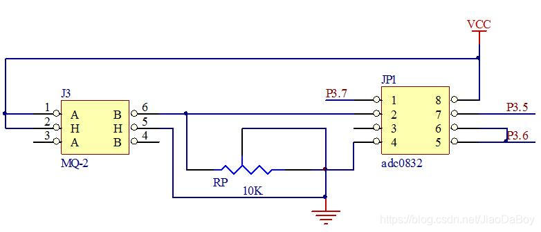
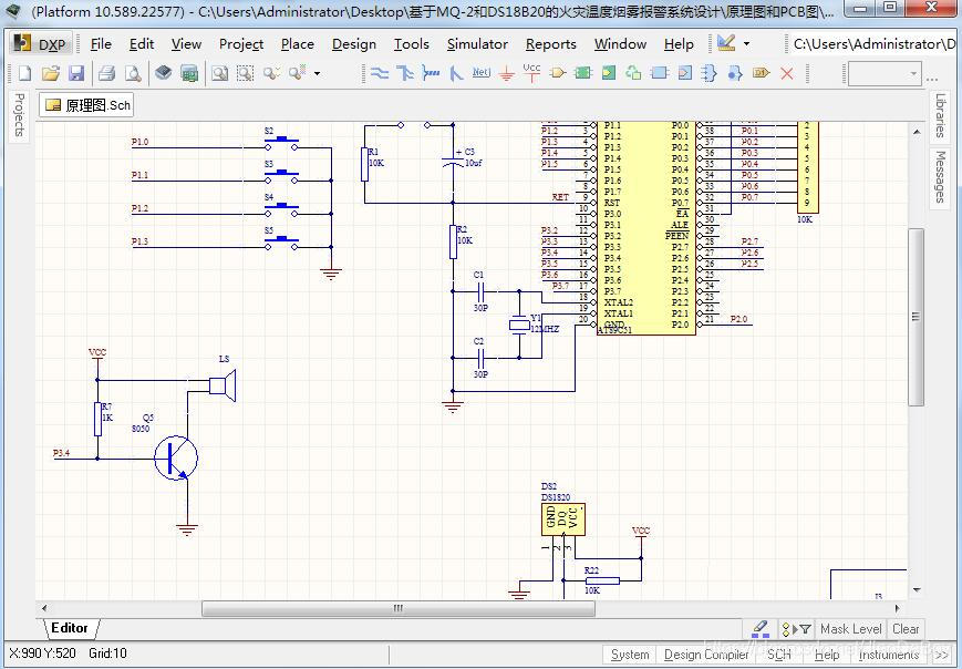
In practical application, in the schematic diagram, the wiring method of MQ-2 is shown in the following figure.
Since the output voltage of MQ-2 is not linear with the smoke concentration, the ratio of Rs/R0 needs to be calculated according to the above calculation formula, and then the sensitivity characteristic curve table is obtained. -2 Operating instructions for voltage-concentration conversion.

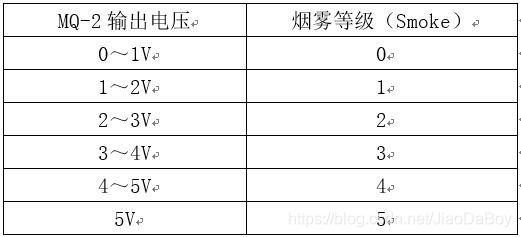
Simulation In order to simplify the process, the smoke level (Smoke) is divided into 5 grades, and the corresponding relationship with the MQ-2 output voltage is shown in the following table.
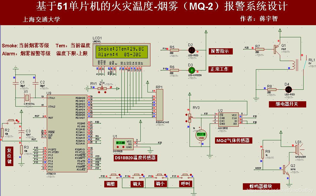
Simulation circuit schematic diagram and analysis of physical simulation results of
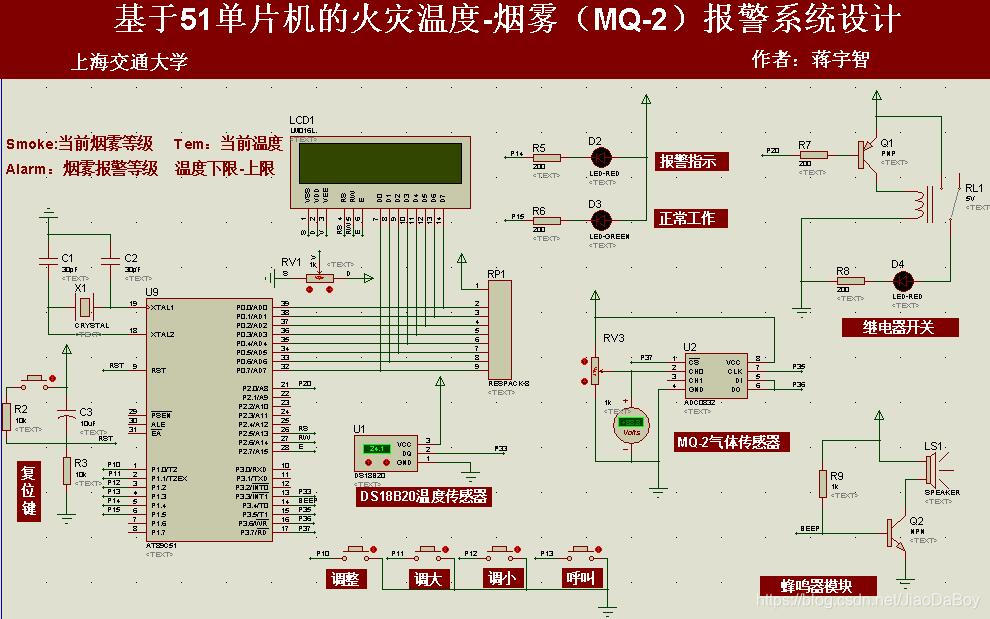
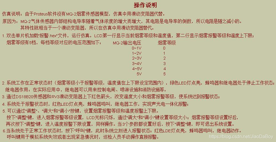
PCB perforated board Open the simulation file "Design of Fire Temperature Smoke Alarm System. DSN", double-click the single-chip microcomputer to load the "Alarm.hex" file, and run the simulation. The results are as follows. As can be seen from the figure, the LCD shows that the current smoke level is 3, which is lower than the set alarm level 4; the current temperature of the system is 29.8°C, which is within the temperature range (5-30°C); the green LED light is on, indicating that the system is in Under normal working condition; the relay and buzzer are in the working stop state.

By adjusting the DS18B20 sensor and the RV3 sliding rheostat with the up and down red arrows, the temperature or smoke level can be changed to make the system reach the alarm state. At this time, the simulation results are shown in the following three figures.
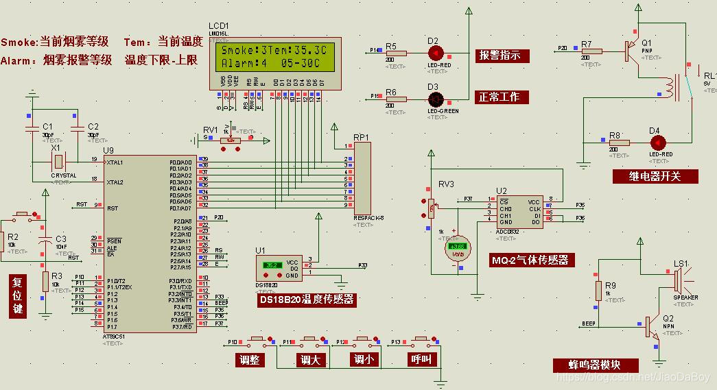
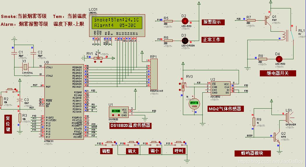

It can be seen from the above 3 alarm states that no matter whether the temperature or smoke alarms individually or simultaneously, the system action is the same, that is, the red LED alarm indicator lights up, the buzzer sounds, and the relay operates, achieving an integrated sound and photoelectric system. Alarm action.
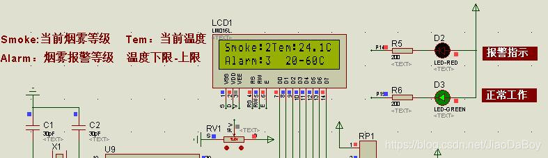
You can set the smoke alarm level and the upper and lower limits of the temperature alarm by pressing the "adjust", "larger" and "smaller" buttons. Press the "Adjust" key to enter the smoke alarm level setting, the LCD cursor flashes, and use the "Enlarge" and "Down" keys to set the level size; after the setting is completed, press the "Adjust" key again to enter the temperature alarm lower limit setting , do the same. When the three parameters are set, press the "Adjust" key to exit the system settings.
In this example, we set the smoke alarm level to 3 and the temperature range to 20-60°C, the result is shown in the figure.
When the system is in normal working state, press the "call" button, and the system immediately enters the alarm state: the red LED lights up, the buzzer sounds, and the relay operates. The call key is used to simulate system failure or emergencies, and the inspection personnel can manually operate and directly alarm.
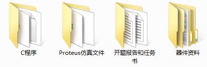
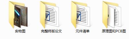
The resources shared are
(1) the full version of the design paper of fire temperature smoke alarm system based on MQ-2 and DS18B20;
(2) Keil C program;
(3) Proteus simulation file;
(4) Proposal report and assignment book;
(5) Device information;
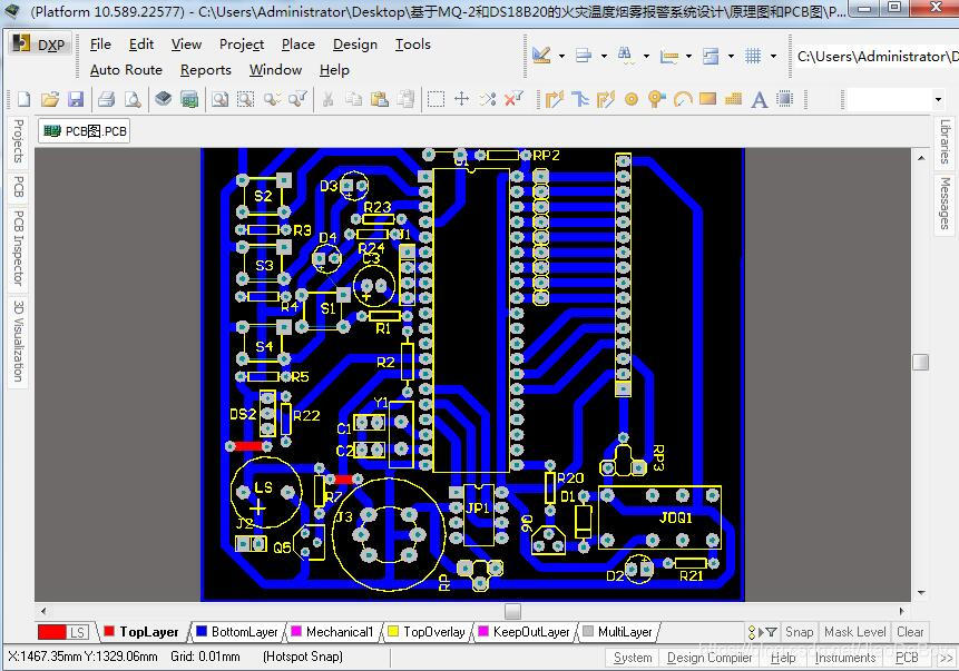
(6) Schematic diagram and PCB file;
(7) Component list;
(8) Physical map;
The full set of resources are as follows
. Important things to say again! ! !
Get a complete set of design materials for the design of fire temperature-smoke alarm systems based on MQ-2 and DS18B20!
Please search on WeChat and follow my official account: Jiaoyuan Xiaozhi